Chapter 1: THE NEW YORK CITY WORLD TRADE CENTER BUILDING 7
1.1 THE WORLD TRADE CENTER COMPLEX The New York City World Trade Center (WTC) complex was located in Lower Manhattan, just north of Wall Street, in the heart of the financial district. It was built by The Port of New York Authority, later to be renamed as The Port Authority of New York and New Jersey (The Port Authority, PANYNJ). Created in 1921, under a clause in the United States Constitution, to run the multi-jurisdictional commercial zones in the region, The Port Authority built and operated facilities on the banks of the Port of New York's waterways, the bridges to cross them, and the major metropolitan airports. It has the authority to obtain land by eminent domain, raise funds for its projects, and to construct under its own building code. Nonetheless, The Port Authority policy was to comply with the local building code in place at the time of building design, which, for the WTC complex, was the 1968 version of the New York City Building Code (NYCBC).
The original WTC complex consisted of six buildings (Figure 1- 1). The two towers, WTC 1 (North Tower) and WTC 2 (South Tower), which provided the iconic appearance of the complex, were each 110 stories high, dwarfing the other skyscrapers in lower Manhattan. WTC 3, a Marriott Hotel, was 22 stories tall, WTC 4 (South Plaza Building) and WTC 5 (North Plaza Building) were each nine story office buildings, and WTC 6 (U.S. Customs House) was an eight story office building. These six buildings were built around a five acre Plaza. Construction began in 1968, with the first occupancy in 1970.
Commuter trains brought tens of thousands of workers and visitors to Manhattan from Brooklyn and New Jersey into a new underground station below the plaza. A series of escalators and elevators took the WTC employees directly to an underground shopping mall and to the Concourse Level of the towers.
1.2 WTC 7
1.2.1 The Edifice In 1967, a Consolidated Edison of New York (Con Edison) substation had been built on Port Authority land on the north side of Vesey Street, between Washington Street on the west, West Broadway on the east, and Barclay Street on the north. This substation would distribute electrical power to Lower Manhattan. In designing the substation, provision was made for a future office tower by including structural capacity to carry the weight of both the substation and the future high-rise building. Twenty years later, the high-rise building, designated WTC 7, was completed. The architectural design was performed by Emory Roth & Sons, P.C. The structural engineer of record was the Office of Irwin G. Cantor, and the mechanical engineer was Syska & Hennessy, P.C. Tishman Construction Corporation was the general contractor. The building was owned by Seven World Trade Company and Silverstein Development Corporation, General Partners.
This 47 story office building was located immediately to the north of the main WTC Complex, approximately 105m (350 ft) from the north side of WTC 1 (Figure 1-1). It was connected to the WTC complex with a 37 m (120 ft) wide elevated plaza, known as the Promenade, at the 3rd floor level, and a 6.7m (22 ft) wide pedestrian bridge, also at the 3m floor level. Figure 1-2 is a photograph of the WTC site, showing the relationship of WTC 7 to the surrounding buildings.
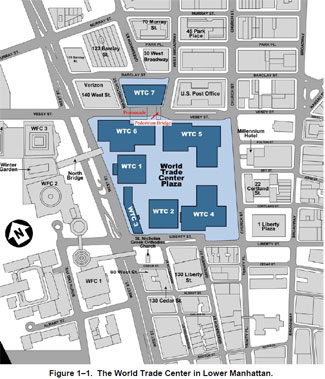 Figure 1-1. The World Trade Center in Lower Manhattan.
 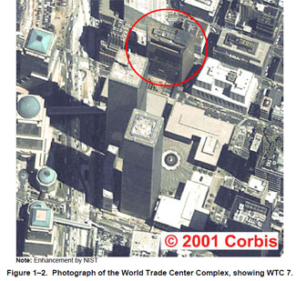 Note: Enhancement by NIST
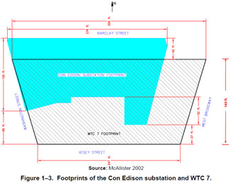
Figure 1-2. Photograph of the World Trade Center Complex, showing WTC 7. 1.2.2 The Con Edison Substation The Con Edison substation was a steel-framed structure with cast-in-place concrete floors and walls. It was placed on the northern portion of the site and extended approximately 13 m (42 ft) north of the north facade of WTC 7, as shown in Figure 1-3. Its southerly boundary was irregular, but extended approximately two-thirds of the width of WTC 7. The Con Edison Substation was two stories in height, coinciding with the first two floors of WTC 7 (Figure 1-4). Details of the construction and the function of the substation can be found in NIST NCSTAR 1-9, Chapter 2, and Appendix A, respectively.
WTC 7 and the electrical substation were supported on caisson foundations, which were seated in the bedrock, approximately 20 m (60 it) below the surface. Above the caissons were heavy grillages composed of built-up steel girders. The 2.5 m to 9 m (8 it to 30 ft) distance between the caissons was braced by reinforced concrete walls with thicknesses varying from 0.3 m to 0.8 m (1 ft to 2.5 it). Many of the WTC 7 steel columns were embedded in these walls. The areas between the concrete walls were filled with compacted gravel fill and then covered with a concrete slab to form closed cells and bring the structure up to the required elevation. In some cases, the area was left untilled and used to house fuel tanks.
 Source: McAllister 2002
Figure 1-3. Footprints of the Con Edison substation and WTC 7. 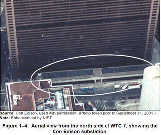 Source: Con Edison, used with permission. (Photo taken prior to September 11, 2001.)
Note: Enhancement by NIST
Figure 1-4. Aerial view from the north side of WTC 7, showing the Con Edison substation. Within the substation were nine transformer vaults that housed the units that converted the 138 kV incoming power to 13.8 kV for transmission throughout Lower Manhattan. Access within the substation was provided by stairwells on the west side, in the center, and on the east side of the building. None of these stairs extended into the 47-story building above. In fact, concrete walls fully separated the substation from WTC 7.
1.2.3 The Structure WTC 7 was an irregular trapezoid, approximately 100 m (329 ft) long on the north face and 75m (247 ft) long on the south face, 44m (144 ft) wide, and 186m (610 ft) tall. The 47 story building contained approximately 200,000 m[2] (2 million ft[2]) of floor area. A typical floor was similar in size to a football field. The gross floor area was about 75 percent of that contained in the Empire State Building. As shown in Figure 1-3, about half of WTC 7 rose outside the footprint of the Con Edison substation. Structurally, WTC 7 consisted of four "tiers."
• The lowest four floors housed two two-story lobbies, one each on the center of the south side of the 1st and 3rd floors. The north side of the 1st and 2nd stories was the Con Edison substation. The remainder of the north, east, and west sides of these four stories was conference space, offices, a cafeteria, etc.
• Floors 5 and 6 were mechanical spaces. Within the volume bounded by the 5th floor slab and the 7th floor slab were three transfer trusses and a series of eight cantilever transfer girders. As their names indicate, these steel assemblies distributed the load of the upper floors of WTC 7 onto the structural frame of the Con Edison substation and the structure of the lowest four floors of WTC 7.
• Floors 7 through 45 were tenant floors, all structurally similar to each other. The exception was a reinforcing belt truss around Floors 22 and 23.
• The 46th and 47th floors, while mainly tenant floors, were structurally reinforced to support special loads, such as the cooling towers and the water tanks for fire suppression.
The structural frame was designed to distribute the weight of the building (gravity loads) and resist (lateral) wind loads. The frame included columns, floor assemblies, spandrel beams, girders, and transfer elements.
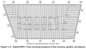
From the 7th floor to the 47th floor, WTC 7 was supported by 24 interior columns and 58 perimeter columns (numbered 1 through 57, plus 14A, which was located near the south end of the west face) (Figure 1-5). Twenty-one of the interior columns (numbered 58 through 78) formed a rectangular building core, which was offset toward the west of the building. The remaining three interior columns (79, 80, and 81) were particularly large, as they provided support for the long floor spans on the east side of the building.
In the final design of WTC 7, the layout of the columns did not align with the building foundation and the Con Edison columns. Therefore, a set of column transfers were constructed within the volume bounded by the 5th and 7th floor slabs. These are depicted in Figure 1-6, along with the numbers of the columns to which they connected.
 Based on structural drawings (Cantor 1985)
Figure 1-5. Typical WTC7 floor showing locations of the columns, girders, and beams. 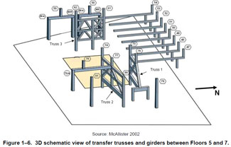 Source: McAllister 2002
Figure 1-6. 3D schematic view of transfer trusses and girders between Floors 5 and 7. The floor slabs were reinforced concrete of varying thickness. The 1st floor slab was 0.36 m (14 in.) thick. The concrete on almost all of the other floors was poured on top of 76 mm (3 in.) deep corrugated metal decking. Floors 2, 3, 4, and 6 had a 0.15 m (6 in.) total slab thickness; on Floor 5, the concrete was 0.36m (14 in.) thick; and all Floors 8 through 47, the concrete was 0.14 m (5.5 in.) thick. On Floor 7, the south half of the floor had a poured 0.2 m (8 in. ) slab, and the north half had an 0.2 m (8 in.) total slab thickness on a 76 mm (3 in.) deep metal deck. The floor slabs were supported by the structural floor framing shown in Figure 1-5. The floor beams were connected to the concrete deck by shear studs, which caused the floor beams and concrete slab to act together, or compositely. This type of floor system is thus referred to as a composite floor. The floor beams were framed into (connected to) girders with a variety of types of shear connectors [1], through which the floor beams transferred gravity loads from the floors to the girders. The girders also framed into the columns with a variety of types of shear connectors and transferred the gravity loads to the columns. Interior columns were connected with splice plates, welds and bolts. The exterior frame had moment connections in each face of the building.
1.2.4 Fire Protection There were both passive and active fire protection systems in WTC 7 (NIST NCSTAR 1-9, Chapter 4). The former was in the form of sprayed fire-resistive material (SFRM) applied to the structural steel and to the underside of the metal floor decking. The latter comprised fire sensors and alarms, notification systems, automatic fire sprinklers, water supplies, and smoke management.
According to the 1968 version of the NYCBC and Local Law 16 (1984), a fully sprinklered high-rise building could follow the fire resistance requirements for Type I C construction. For this construction category, columns were required to have a 2 h rating as established by the Standard Fire Test (ASTM E 119); beams were required to have a 1-1/2 h rating. The instructions to the bidders for the WTC 7 job were to bid on a 3 h rating for the columns and a 2 h rating for the metal deck and floor support steel, which corresponded to the more stringent fire resistance requirements for Type IB (unsplinklered) construction. These ratings were to be achieved by application of Monokote :MK-5, a gypsum-based SFRM that contained a vermiculite aggregate. According to the Underwriters Laboratories (UL) Fire Resistance Directory (1983), these ratings required a thickness of 22 mm (7/8 in.) of Monokote MK-5 to be applied to the heavy columns, 48mm (1-7/8 in.) to be applied to the lighter columns, 13 mm (1/2 in.) to be applied to the beams, and 10 mm (3 /8 in.) to be applied to the bottom of the metal deck. Private inspectors found that the applied SFRM thicknesses were consistent with these values.
Within the building was an array of smoke detectors which, when triggered, would sound alarms on the floor of detection and the floor above, provide an alarm and signal location to the Fire Command Station in the 3rd floor lobby, and transmit a signal to the fire department. There were barriers to smoke spread (in the form of walls and smoke dampers), as well as air movement equipment to exhaust the smoke.
WTC 7 contained a three-zone system of sprinklers and standpipes.
• Water to the low zone (1st floor through the 20th floor) came from the water main. The backup water also came from the water main via a supplemental pump.
• Water to the mid-level zone (21st floor through the 39th floor) was supplied from two large storage tanks located on the 46th floor. Backup water could be pumped from the water main.
• The sources of the primary and backup water supplies to the high zone (40th floor through the 47th floor) were the same as for the mid-level zone.
The NYCBC requirement was for a 30 min water delivery duration at a delivered density of 0.04 L/min_m[2] (0.10 gal/min-ft[2]), and Investigation calculations determined that the installed system met these requirements. This would have been sufficient to control fires of four clusters of six workstations each, either all on one floor or single clusters on four floors.
These fire protection measures addressed the conventional approaches to preserving life safety. However, in the U.S., neither architectural nor structural engineering practice explicitly required (then or currently) an evaluation of the structural system response to heating (fires) as part of the building design.
1.2.5 The Workplace Many of the roughly 8,000 people who worked in or visited WTC 7 on a given day would have arrived via trains that stopped in the large station under the main WTC complex. They could enter the first floor of the building through street-level doors along Vesey Street, Washington Street, and West Broadway. Alternatively, from the main WTC complex, they could cross Vesey Street via the Promenade or the covered pedestrian bridge and enter the 3rd floor lobby of the building.
Within the building core were 32 elevators, 28 of which would have taken them to their various offices. The floors that the elevators served are indicated in Figure 1-7.
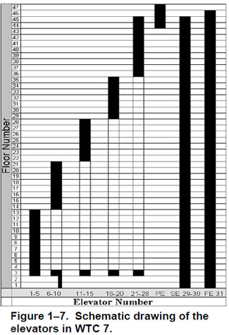 Figure 1-7. Schematic drawing of the elevators in WTC 7.
There were also two stairwells, each 1.42 m (56 in.) to 1.47 m (58 in.) wide. The west stairwell was entered through a side door on Washington Street. The stairs rose to the 5th floor, where there was a short transfer corridor. From there, the stairs were vertically continuous to the 47th floor. The east stairwell was entered from West Broadway and had transfer corridors on the 5th and 23rd floors, before continuing to the 47th floor.
WTC 7 was operated by Silverstein Properties, Inc., from the date of its completion. Table 1-1 indicates the tenants of WTC 7 as of September 11, 2001.
Table 1- 1. Use of floors in WTC 7
Floor(s) / Tenant or Function [a]
46, 47 / Mechanical space, Citigroup
26 through 45 / Citigroup
25/ U.S. Internal Revenue Service, Department of Defense, Central Intelligence Agency
24 / U.S. Internal Revenue Service
23 / New York City Mayor's Office of Emergency Management (OEM)
22 / Federal Home Loan Bank of New York
21 / First State Management Group
19 through 21 / The Hartford Insurance Company 18 / Equal Employment Opportunity Commission, Teleport, Metropolitan Fiber Systems
15 through 17 / Citigroup
14 / Vacant
13 / U.S. Securities and Exchange Commission, Provident Financial Management. American Express
11, 12 / U.S. Securities and Exchange Commission
10, 9 / U.S. Secret Service
7, 8 / American Express
5, 6 / Mechanical floors
4 / Meeting spaces, cafeteria
1 through 3 / Lobbies, conference center
a. Among those interviewed by the Investigation Team, there was limited recollection of the organizations occupying some of the floors, especially those occupying smaller spaces, and no one had copies of all the tenant leases.
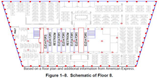
1.2.6 The Combustible Contents The layout of most of the floors featured clusters of workstations, or cubicles, throughout the space surrounding the building core (NIST NCSTAR 1-9, Chapter 3). Often, there were walled offices at the perimeter. The layout in Figure 1-8 is indicative of these floors. While there were almost certainly different types of workstations in the building, they were all fundamentally similar. Each cubicle typically was bounded on four sides by privacy panels, with a single entrance opening. Within the area defined by the panels was a self-contained workspace: desktop (almost always a wood product, generally with a laminated finish), file storage, bookshelves, carpeting, chair, etc. Presumably there were a variety of amounts and locations of paper, both exposed on the work surfaces and contained within the file cabinets and bookshelves.
The combustible fuel load [2] for these open landscaped floors was dominated by the workstations. The architectural drawings showed densities of workstations similar to those on most of the fire floors in the WTC towers. The estimated combustible fuel load for these floors was about 20 kg/m[2] (4 lb/ft[2]). Simulations of the fires with a higher combusted fuel load (NIST NCSTAR 1-9, Chapter 9) resulted in poor agreement with the observed fire spread rates.
 Based on a floor plan and additional information from American Express.
Figure 1- 8. Schematic of Floor 8.On a number of other floors. the space was almost completely subdivided into individual offices. A typical layout is depicted in Figure 1- 9.
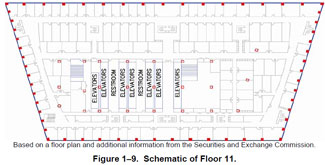 Based on a floor plan and additional information from the Securities and Exchange Commission.
Figure 1-9. Schematic of Floor 11. On the 11th and 12th floors, which will be seen later to have been the sites of significant and sustained fires, the mass of additional paper materials was described as very high. As indicated in NIST NCSTAR 1-9, Chapter 3, the Investigation Team estimated a combustible fuel load of approximately 32 kg/m[3] (6.4 lb/ft[2]). Simulations of the fires with a lower combustible fuel load showed little effect on the rate of fire progression.
Unlike the case for the two WTC towers, there was no widespread spraying of jet fuel to ignite numerous workstations or offices simultaneously. Rather, in the earlier hours of the fires, following the debris impact due to the collapse of WTC 1, the fire would have spread from one individual workstation or office to another. [3] Thus, the fire spread would have been dependent on the office walls, the specific spacing of the cubicles, the ease of ignition of the furnishings, their combustible mass, and the extent of surface occlusion by foreign matter.
There were emergency power generators in WTC 7 (NIST NCSTAR 1-1J). The diesel fuel for these generators was stored within and under WTC 7. Properties of the emergency power systems are summarized in Table 1-2.
Table 1-2. Emergency power systems in WTC 7.
-- / Base Building System / Salomon Brothers System [4] / Mayor's OEM System
Fuel Storage Tank Capacities / Two 12,000 gal tanks / Two 6,000 gal tanks / Single 6,000 gal tank
Tank Locations / Below the loading dock / Below the loading dock / 1st floor
Locations of Generator(s) / Two on 5th floor / Nine on the 5th floor / Three on the 7th floor
Day Tanks and Locations / Single 275 gal tank on the 5th floor / None [a] / Single 275 gal day tank on the 7th floor
Day Tank Pump Locations and Capacities / Two on the 1st floor; 4.4 gal/min / Two circulating pumps on 1st floor, 70 gal/min / Two on the 1st floor, 12 gal/min
Ambassador (U.S. Secret Service) Modification / Generator and 50 gal day tank on 9th floor; two pumps on the 1st floor, 2.4 gal/min / -- / --
American Express Modification / Generator and 275 gal day tank on 8th floor [ b]; two pumps on the 1st floor, 2.8 gal/min
a. The NYCBC had a limit of one day tank per floor. Since there was a day tank on the 5th floor for the base generators, the SSB system used a pressurized fuel distribution system, in which pumps continuously circulated fuel whenever the generators were running. There was enough fuel (35 gal) in the valve rig and piping on the 5th floor to start the diesel engines, which, in turn, would supply power to operate the circulating pumps.
b. The generator and day tank had been removed prior to September 1, 2001.
Figure 1-10 depicts the locations of the electrical generators, the day tanks, and the fuel lines that connected them to the below-ground fuel tanks.
The base building tanks were full on September 11, 2001. Several months following the attacks on the WTC, a contractor recovered an estimated 23,000 gal of fuel from these tanks. NIST estimated that approximately 1000 gal ± 1000 gal was unaccounted. The fate of the fuel in the three day tanks is unknown, so NIST assumed they were full on September 11, 2001.
The fate of the fuel in the two tanks for the Salomon Brothers system was also unknown. Thuss, NIST assumed that all of the fuel would have been available to feed fires either at ground level or on the 5th floor.
No trace of the Mayor's OEM system tank or fuel was found. Since the pumps used to fill the day tank on the 7th floor would only have run when the low fuel switch came on, NIST assumed that all the fuel was available. This tank was enclosed in 4 h fire rated construction and was provided with a total flooding fire suppression system.
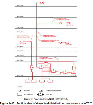 Based on Figure 8-1 from NIST NCSTAR 1-1J
Figure 1-10. Section view of diesel fuel distribution components in WTC 7.1.3 REFERENCESCantor 1985. Irwin G. Cantor P.C., Structural Engineers, Structural Drawings, 7 World Trade Center.
McAllister, T., ed. 2002. World Trade Center Building Performance Study: Data Collection, Preliminary Observations, and Recommendations. FEMA 403. Federal Emergency Management Agency. Washington, DC, May.
_______________
Notes: 1. Shear connections are designed to transfer only vertical gravity loads, whereas moment connections are designed to transfer loads and moments (forces resulting from bending of a beam) induced by both (vertical) gravity and (horizontal) wind loads.
2. In the fire simulations, the entire combustible fuel load can be burned. In actuality, not all of, e.g., a wood desk is consumed. Thus, the combusted fuel loads estimated for these simulations are somewhat lower than the actual fuel loads in prior surveys of office buildings. (See NIST NCSTAR 1-5.)
3. The ingress of dust and debris through broken windows would have slowed this spread, especially near the south face of WTC 7, by depositing on horizontal surfaces and, thus, making ignition more difficult.
4. Renovations were made in 1988 and 1989 to the space leased by Salomon Brothers Inc. in WTC 7. In 1998, Smith Barney Inc. merged with Salomon Brothers Inc. to form Salomon Smith Barney. In 1999, Salomon Smith Barney Inc. merged with Citicorp Inc. to form Citigroup Inc.